
SC2.2 voltage regulator
-
AuthorPosts
-
May 25, 2016 at 11:56 am #15348
Hi, In my SC2.2 I had to replace the L7815CV and the 2N5401 because both were burned…
Now the unit is working again the +v is +15.4v but the –v voltage is -16.8v
Any way to adjust the –v ?
Thanks,
May 26, 2016 at 1:16 pm #16034The power rails on the SC2.2 are derived from a single 15V regulator which is ‘crowbarred’ up to 30V by standing the control 15V above the negative rail. The centre voltage is decided by IC7 which produces a ‘half-rail’ point. So there is no way of setting the negative rail separately. If the voltages are wrong, it’s most likely that IC7 has failed in some way.
I suggest that you replace IC7, and make sure that the 2N5401 is good…. the regulation looks to be slightly off

It’s very unusual to see this sort of fault; it suggests that the unit has been hit with 240VAC with the fuse selector in the 120V position!
May 27, 2016 at 12:25 pm #16035the IC7 is near the vu meter trim adjust? or in front of the release potentiometer? May 27, 2016 at 12:56 pm #16036You can identify the correct IC because it is the only dual op-amp with a 680 ohm resistor between pins 1 and 2. Confusingly, on some slightly later SC2.2 versions, the IC was designated IC9.
On my ‘re-invention’ of the old SC2 (TFPRO P38) I altered the design of the power supply so that it became a true dual supply with two regulators, but some say that the older version with the slightly ‘sloppy’ power supply had a particular character caused by the power supply deficiency! I don’t think so.
All the same there are many hundreds of those old SC2s still in use and they have proved to be reliable…… except for this one!
May 28, 2016 at 11:45 pm #16037I could not find any with a 680ohm between pin 1&2 ,perhaps it is between 6 and 7 ? June 2, 2016 at 7:59 am #16038That’s most likely…. as you can see, I don’t have the layout information for that model, only the circuit diagram. June 17, 2016 at 9:27 am #16039maybe I take a wrong reference point, If referenced to the center pin of the 7815 regulator I get +15.4 and -16.7 , but if I take as a reference the audio ground a get +16 and -16.1, is this correct?
also, the chasis ground is connected to audio ground only through the locking screw in the xlr connector?
With the unit opened , measured 64v AC between the chassis ground and audio ground….
June 18, 2016 at 7:50 am #16040Yes, that is correct…. the centre pin of the regulator is not the same as the ground reference. if you are measuring + and – 16V approx, then it’s all doing its job. As for grounding, on more recent compressors I made sure that the chassis was bonded (as they say) to the ground pin on the mains socket, the audio ground was left floating and only connected to the ground connections of the inputs and outputs. This is the classic grounding system that works in most instances.
Back in the days of the SC2.2 it’s possible that the grounding was less carefully done.
I suggest that you make sure that the chassis is well connected to the mains ground pin.
In smaller installations it’s generally OK to have the audio ground common with the mains ground, but there is then the danger of ground loops and consequent hum.
June 28, 2016 at 9:54 am #16041the chassis is grounded to mains ground. the potentiometer shields on the front panel sholud be connected to the chassis ? now the green paint is insulating the connection between them
June 30, 2016 at 9:31 pm #16042It’s normal for the pot bodies to be connected to the front panel of course, (connection is normally through ‘shakeproof’ washers), but even if they are not, it’s unlikely to affect performance in any way. July 1, 2016 at 12:12 pm #16043I have a low level hum on the rigth output only, any idea where to look ? July 1, 2016 at 4:03 pm #16044I can’t diagnose that from the description ‘low level hum’. How low? is it 50Hz or 100Hz? Hum is usually a power supply problem; or more likely, a ground path problem, and it’s often associated with things external to the equipment, particularly as the hum is on one output only. With equipment of this vintage (up to 2002 say), you can never ‘cure’ hum, you can only minimise it. Nowadays with switch-mode power supplies the designer can eliminate it.
Dealing with hum on older equipment can be very complex, but on the other hand, the SC2 compressors are relatively simple and don’t have high-gain stages so it’s unusual to find it as a problem.
First, be sure that the problem is not external to the compressor.
July 2, 2016 at 8:51 pm #16045first of all thanks for your patience and time. well, I made a test , on inputs a 600ohm resistance on pins 2&3 and outputs direct to computer,no ground loops,tested with different cables and always same result
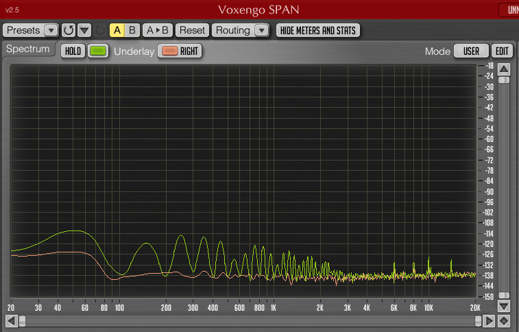
http://www.vaporstudio.com/studio/joemeek1.jpg
" /> if it would be a power supply, it would be on booth channels no?
July 3, 2016 at 8:13 am #16046The trace you sent shows multiple harmonics of the 50Hz but with the first harmonic (100Hz)as a minimum. This indicates to me that the ‘problem’ (if it is a problem) is a function of the ground paths around the integrated circuits at the input. It is not a simple case of power supply noise. Also from the traces I can see that the level of hum is extremely low….. is it audible at all? If the traces refer to 0dB as a reference, then the noise cannot be audible.
The noise performance of the input stages are very reliant on the quality of the ground connection on the positive inputs of IC1 and IC2; there is one pin on each of those ICs that is connected to ground. (I can’t tell you if it’s pin 3 or pin 5… I don’t have that info.) If you can establish by examination which pin it is on each IC, then it might be a plan to link those pins so that the ground is the same on each.
July 7, 2016 at 9:13 am #16047checked the input ICs and it is the pin 5 that is connected to ground, linked both pins but no changes… the noise buzz not follow the input gain pot, if gain increased only white noise goes up the buzz stays at same level, but with the gain output pot it increase/decreases.
-
AuthorPosts
- You must be logged in to reply to this topic.